Week 6
This week's work was mainly focused on reconstructing the assembly for the entire straight section of track from last year's team. The files they passed on had the entire track with truss as one solid part, while their additions of the support columns and stiffening braces on the sides were their own parts. They had pulled the parts out into separate files for their manufacturing quote but never created a new assembly. The only thing left to do to this assembly is to add all the connecting hardware, and colorize the separate components once again.
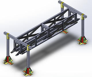


Figure 1: Corrected straight track assembly.
After the truss assembly was finished I began working on our new cross-section design. As the Futran designed track would be extremely difficult, if not impossible to fabricate in a curved fashion we have to develop a design that will be feasible at the small scale we are working at. While we would love to continue using the Futran track design itself, we do not have the facilities to manufacture it curved and still have not received work if Futran has a compatible design for turns. And if it turns out that they do, we can not rely on outside sources to get the designs or files needed in the time frame that is required for our project. So going along this idea we came up with the cross-section show in figure 2 below. In order to keep the dimensions as close to the Futran design as possible, it is constructed with two 8" x 2", and one 2" x 4" rectangular steel tubes. This will allow us to get them bent to the required radius, as shown in figures 3 and 4 below, before assembly when we can weld the three sections together. While this design will likely not be as strong or long-lasting as the Futran design, it should be more than sufficient for our full-scale model. Once we have finished designing the new mounting brackets for it we will be able to conduct finite element analysis and see how strong it turns out to be. It may turn out that it will be strong enough for full-time use with the addition of Hardox wear plates on top and bottom like the Futran design.

Figure 2: Cross-section of new track design.

Figure 3: Design of inner curved section of track leaving the junction.

Figure 4: Design of outer curved section of track leaving the junction.

Figure 5: Design of straight section of track.
In the coming week I will be working on designing the new mounting brackets for this track design, as well as the junction itself. Once those designs are put together we will be able to create a working assembly of the junction itself that we can implement our third rail design onto.
Comments
Post a Comment